• ComputerBase erhält eine Provision für Käufe über eBay-Links.

Ambilight zum Nachrüsten (60-128 Channels je nach TV)

Ist aber recht teuer das ganze muss ich sagen...
3 Pixel für 7,70, macht für 50 Pixel ca. 130€. Der Chinese liefert einen 50 Pixel für 30€ + -(WS2801 IC) , dazu ein Arduino + Netzteil und Adalight und man ist noch immer deutlich drunter würde ich behaupten. Ich weiß nicht ob die Samsung LEDs das rechtfertigen aber ich würde mal sagen die China teile dürften das auch machen siehe hier:

http://www.youtube.com/watch?v=fM-CBL7nrbE


Ansonsten: Nette Spielerei aber sonst unnötig.
 
Interessantes Thema,

habe einen HTPC mit einem AsrockE350m1 gebaut als System nutze das OpenELEC Mediacentre alias XBMC.
Ich wollte mir auch mal ein Ambilight mit einem Arduino zusammenbauen leider kam es nicht dazu.
Beim OpenELEC Mediacentre gibt es ja noch das Plugin für Boblight aber ich weis leider ncith wie ich das Bewerkstellige das dies geht.

Habe noch ein Arduino UNO rev 3 board. und um meinen 40 Zoll LCD an der seite LED Stripes befestigt die ich momentan noch nicht Automatisch ansteuere nur manuel mit einer Fernbedienung.

Cool fände ich es wenn nicht viele Ferben agenzeigt werden sonder nur die Durchschnittsfarbe vom gespielten Bild, quasi nur ein eingepasster hintergrund. Funktioniert das mit meinem HadwareSetup ? und vorallem was brauch ich alles dazu ?

Edit: Für Windows gibts ein Programm das eine RGB LED auf dem ArduinoBoard steuert da wird immer nur eine Farbe (Durchschnittsfarbe) ausgegeben.

Könnte jemand vll einen Link posten wenns sowas schon fertig gibt?
 
Zuletzt bearbeitet:
Piquard schrieb:

hmmm soweit sogut hab mir mal soein bestellt http://www.ebay.de/itm/USB-zu-TTL-Konverter-Adapter-Modul-PL2303HX-3V-oder-5V-/161186503008?pt=LH_DefaultDomain_77&hash=item258776d960 blos ich denk nicht, dss der strom von einem USB anschluss ausreicht vll für 3 LEDs aber ich hab einen kompletten stripe um meinen TV (40") wie befeuer ich den mit extrastrom, einfach das Netzteil an die 12v +pol hängen ?
 
Zuletzt bearbeitet:
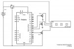
Für die Ansteuerung der LEDs müsstest du Leistungstransistoren oder FETs nehmen

etwa so:

RGB-LED-Strip-Circuit.jpg
 
Piquard schrieb:
Für die Ansteuerung der LEDs müsstest du Leistungstransistoren oder FETs nehmen

etwa so:

Anhang anzeigen 389688

Danke für deine Antwort, war gestern bei einem Kupel der hat bei Seinem TV einfach dahinter eine Ultrahelle LED wie er sagte bei ihm leider nur einfarbig, was werde ich als erstes auuch mal anpeilen, das ich nicht meinen Kompletten stripe hinfummle sondern nur eine LED halt ultrahell und RGB,, das funktioniert doch eigenltich schon an den USB connector den ich gespostet habe oder brauch ich dazu auch das Arduino? Die zusätzliche stromquelle entfällt dann ja auch oder ?
Gibt ja bei Amazon, Ebay , Reichet so ultrahelle RGB LED´s....

Dann werde ich eher sowas basteln das ich keine komplette riesensteuerung brauche
 
AW: Ambilight bis 256 Channels für Windows / Linux / DreamBox /VU+ / ET

Kennt sich jemand mit den Arduinos aus? Der uno r3 ist zu klein für 166 LEDs. Ich hab ein flackern im letzten Stripe und es liegt wohl daran, dass der Uno es nicht packt. Welcher ist leistungsstärker? Oder hat jemand mehr als 120 LEDs mit dem Uno r3 laufen?
Ich weiß nicht ob der Mega mit mehr Speicher reicht oder der Leonardo mit schnellerer Ansprechzeit über USB... Oder vll doch was größeres.
 
AW: Ambilight bis 256 Channels für Windows / Linux / DreamBox /VU+ / ET

Schicksal schrieb:
Kennt sich jemand mit den Arduinos aus? Der uno r3 ist zu klein für 166 LEDs. Ich hab ein flackern im letzten Stripe und es liegt wohl daran, dass der Uno es nicht packt. Welcher ist leistungsstärker? Oder hat jemand mehr als 120 LEDs mit dem Uno r3 laufen?
Ich weiß nicht ob der Mega mit mehr Speicher reicht oder der Leonardo mit schnellerer Ansprechzeit über USB... Oder vll doch was größeres.

hänge doch auch wie ich es moechte eine RGB LED hin blos halt ultrahell oder hast du einzelne kanäle?
 
AW: Ambilight bis 256 Channels für Windows / Linux / DreamBox /VU+ / ET

Schicksal schrieb:
Alles einzelne Kanäle.

hmm ok willst in deinem Falle ein Ambylight von PHILIPS kopieren :) wollt ich auch aber
a) ist mir zu viel aufwand
b) nerv iwie hab ich gemerkt als ich bei eim Kollege war und nen FIlm geschaut hab nach 2h oder so nervts dieses riesen Farbenspiel

darum einfach ein licht dahinter mit der gezeigten Durchschnittsfarbe
hoffe das geht mit dem xbmc / OpenELEC boblight plugin

darum will ich Nur eine RGB LED (superhell) in der mitte hinhängen fertig.
Aber schon daran scheiterts weil ich auf dem gebiet E Technik in der Schule ned richtig aufgepasst habe :/ :s

vll gehts mit dem controller den ich mir gestern bestellt habe wäre cool weils ist ja nur eine LED bzw soll eine werden , einer ein plan ob das geht wie ich mir das vorstelle?

controller ->http://www.ebay.de/itm/USB-zu-TTL-Konverter-Adapter-Modul-PL2303HX-3V-oder-5V-/161186503008?pt=LH_DefaultDomain_77&hash=item258776d960&clk_rvr_id=571561267908

-> für Hilfe wäre ich dankbar :-) :D :) :volllol: (Skizze von einem Schaltplan für meine Ministeuerung vll :D )

in meiner Vorstellung hängt die LED an dem kleinen COntroller (ebaylink) der wiederrrum am HTPC via USB hängt und die Lampe kommt hinten in die mitte vom TV, z.B. da wo die Gewinde für die vesa Halterungen sind.
 
Zuletzt bearbeitet:
ehhhh nee, bei 60 zoll der 5cm von der wand weg ist, ist nichts mit einer LED.
Bei mir läuft übrigens MediaPortal mit Atmowin, hab mich nur nach hier verirrt, weil die
Informationen zum Arduino rech spärlich sind.
 
bissl größer :p, 1 LED geht noch gerade bei 40Zoll das alles so quasi "flavored by color in room" ist nur so hintergrund bissl einpassen ... mehr solls nicht sein weil immer eine weisse Wand ist manchmal langweilig, je nach Film....

aber ob das mit dem oben verlinkten controller geht weis ich nicht.... :( eigentlich muss die LED ja nur an den 3 Ports angeklemmt werden und das XBMC Plugin aktiviert werden oder ? ist doch im Prinzip nichts andres wie wenn ich eine LED ans Arduino klemme oder doch ?! :S :/
 
Zuletzt bearbeitet:
@MegaCayman: den USB-Serial-Adapter brauchst Du nur, wenn Du den Ikea-Dioder ansteuern willst. Für die normalen RGB-Streifen kannst du 3-Analogausgänge vom Arduino nehmen und die Transistoren (oder FETs) steuern. Den Code für die Ansteuerung (für eine einheitliche Farbe) meine ich, auf https://code.google.com/p/ambilight-4-mediaportal/ gesehen zu haben.


Ich habe in letzter Zeit auch etwas mit dem Arduino-Board rum experementiert und bin echt begeistert. Hab noch vor mein SEDU-Board mit dem Arduino zu ersetzen und an dem auch meine normalen 12V-RGB-Streifen anschließen. Mit einer FB für Arduino kann man bestimmt noch so einiges "anstellen" :)

mit dem "Colorswirl" Testprogramm hab ich folgende Resultate mit meinem 106 Pixel WS2801-Steifen bekommen:


1. Über SPI mit einem Ringbuffer implementierte Lösung (142 fps)

Code:
// Arduino "bridge" code between host computer and WS2801-based digital
// RGB LED pixels (e.g. Adafruit product ID #322).  Intended for use
// with USB-native boards such as Teensy or Adafruit 32u4 Breakout;
// works on normal serial Arduinos, but throughput is severely limited.
// LED data is streamed, not buffered, making this suitable for larger
// installations (e.g. video wall, etc.) than could otherwise be held
// in the Arduino's limited RAM.

// Some effort is put into avoiding buffer underruns (where the output
// side becomes starved of data).  The WS2801 latch protocol, being
// delay-based, could be inadvertently triggered if the USB bus or CPU
// is swamped with other tasks.  This code buffers incoming serial data
// and introduces intentional pauses if there's a threat of the buffer
// draining prematurely.  The cost of this complexity is somewhat
// reduced throughput, the gain is that most visual glitches are
// avoided (though ultimately a function of the load on the USB bus and
// host CPU, and out of our control).

// LED data and clock lines are connected to the Arduino's SPI output.
// On traditional Arduino boards, SPI data out is digital pin 11 and
// clock is digital pin 13.  On both Teensy and the 32u4 Breakout,
// data out is pin B2, clock is B1.  LEDs should be externally
// powered -- trying to run any more than just a few off the Arduino's
// 5V line is generally a Bad Idea.  LED ground should also be
// connected to Arduino ground.

// --------------------------------------------------------------------
//   This file is part of Adalight.

//   Adalight is free software: you can redistribute it and/or modify
//   it under the terms of the GNU Lesser General Public License as
//   published by the Free Software Foundation, either version 3 of
//   the License, or (at your option) any later version.

//   Adalight is distributed in the hope that it will be useful,
//   but WITHOUT ANY WARRANTY; without even the implied warranty of
//   MERCHANTABILITY or FITNESS FOR A PARTICULAR PURPOSE.  See the
//   GNU Lesser General Public License for more details.

//   You should have received a copy of the GNU Lesser General Public
//   License along with Adalight.  If not, see
//   <http://www.gnu.org/licenses/>.
// --------------------------------------------------------------------

#include <SPI.h>

// LED pin for Adafruit 32u4 Breakout Board:
//#define LED_DDR  DDRE
//#define LED_PORT PORTE
//#define LED_PIN  _BV(PORTE6)
// LED pin for Teensy:
//#define LED_DDR  DDRD
//#define LED_PORT PORTD
//#define LED_PIN  _BV(PORTD6)
// LED pin for Arduino:
#define LED_DDR  DDRB
#define LED_PORT PORTB
#define LED_PIN  _BV(PORTB5)

// A 'magic word' (along with LED count & checksum) precedes each block
// of LED data; this assists the microcontroller in syncing up with the
// host-side software and properly issuing the latch (host I/O is
// likely buffered, making usleep() unreliable for latch).  You may see
// an initial glitchy frame or two until the two come into alignment.
// The magic word can be whatever sequence you like, but each character
// should be unique, and frequent pixel values like 0 and 255 are
// avoided -- fewer false positives.  The host software will need to
// generate a compatible header: immediately following the magic word
// are three bytes: a 16-bit count of the number of LEDs (high byte
// first) followed by a simple checksum value (high byte XOR low byte
// XOR 0x55).  LED data follows, 3 bytes per LED, in order R, G, B,
// where 0 = off and 255 = max brightness.

static const uint8_t magic[] = {'A','d','a'};
#define MAGICSIZE  sizeof(magic)
#define HEADERSIZE (MAGICSIZE + 3)

#define MODE_HEADER 0
#define MODE_HOLD   1
#define MODE_DATA   2

// If no serial data is received for a while, the LEDs are shut off
// automatically.  This avoids the annoying "stuck pixel" look when
// quitting LED display programs on the host computer.
static const unsigned long serialTimeout = 15000; // 15 seconds

void setup()
{
  // Dirty trick: the circular buffer for serial data is 256 bytes,
  // and the "in" and "out" indices are unsigned 8-bit types -- this
  // much simplifies the cases where in/out need to "wrap around" the
  // beginning/end of the buffer.  Otherwise there'd be a ton of bit-
  // masking and/or conditional code every time one of these indices
  // needs to change, slowing things down tremendously.
  uint8_t
    buffer[256],
    indexIn       = 0,
    indexOut      = 0,
    mode          = MODE_HEADER,
    hi, lo, chk, i, spiFlag;
  int16_t
    bytesBuffered = 0,
    hold          = 0,
    c;
  int32_t
    bytesRemaining;
  unsigned long
    startTime,
    lastByteTime,
    lastAckTime,
    t;

  LED_DDR  |=  LED_PIN; // Enable output for LED
  LED_PORT &= ~LED_PIN; // LED off

  Serial.begin(115200); // Teensy/32u4 disregards baud rate; is OK!

  SPI.begin();
  SPI.setBitOrder(MSBFIRST);
  SPI.setDataMode(SPI_MODE0);
  SPI.setClockDivider(SPI_CLOCK_DIV16); // 1 MHz max, else flicker

  // Issue test pattern to LEDs on startup.  This helps verify that
  // wiring between the Arduino and LEDs is correct.  Not knowing the
  // actual number of LEDs connected, this sets all of them (well, up
  // to the first 25,000, so as not to be TOO time consuming) to red,
  // green, blue, then off.  Once you're confident everything is working
  // end-to-end, it's OK to comment this out and reprogram the Arduino.
  uint8_t testcolor[] = { 0, 0, 0, 255, 0, 0 };
  for(char n=3; n>=0; n--) {
    for(c=0; c<25000; c++) {
      for(i=0; i<3; i++) {
        for(SPDR = testcolor[n + i]; !(SPSR & _BV(SPIF)); );
      }
    }
    delay(1); // One millisecond pause = latch
  }

  Serial.print("Ada\n"); // Send ACK string to host

  startTime    = micros();
  lastByteTime = lastAckTime = millis();

  // loop() is avoided as even that small bit of function overhead
  // has a measurable impact on this code's overall throughput.

  for(;;) {

    // Implementation is a simple finite-state machine.
    // Regardless of mode, check for serial input each time:
    t = millis();
    if((bytesBuffered < 256) && ((c = Serial.read()) >= 0)) {
      buffer[indexIn++] = c;
      bytesBuffered++;
      lastByteTime = lastAckTime = t; // Reset timeout counters
    } else {
      // No data received.  If this persists, send an ACK packet
      // to host once every second to alert it to our presence.
      if((t - lastAckTime) > 1000) {
        Serial.print("Ada\n"); // Send ACK string to host
        lastAckTime = t; // Reset counter
      }
      // If no data received for an extended time, turn off all LEDs.
      if((t - lastByteTime) > serialTimeout) {
        for(c=0; c<32767; c++) {
          for(SPDR=0; !(SPSR & _BV(SPIF)); );
        }
        delay(1); // One millisecond pause = latch
        lastByteTime = t; // Reset counter
      }
    }

    switch(mode) {

     case MODE_HEADER:

      // In header-seeking mode.  Is there enough data to check?
      if(bytesBuffered >= HEADERSIZE) {
        // Indeed.  Check for a 'magic word' match.
        for(i=0; (i<MAGICSIZE) && (buffer[indexOut++] == magic[i++]););
        if(i == MAGICSIZE) {
          // Magic word matches.  Now how about the checksum?
          hi  = buffer[indexOut++];
          lo  = buffer[indexOut++];
          chk = buffer[indexOut++];
          if(chk == (hi ^ lo ^ 0x55)) {
            // Checksum looks valid.  Get 16-bit LED count, add 1
            // (# LEDs is always > 0) and multiply by 3 for R,G,B.
            bytesRemaining = 3L * (256L * (long)hi + (long)lo + 1L);
            bytesBuffered -= 3;
            spiFlag        = 0;         // No data out yet
            mode           = MODE_HOLD; // Proceed to latch wait mode
          } else {
            // Checksum didn't match; search resumes after magic word.
            indexOut  -= 3; // Rewind
          }
        } // else no header match.  Resume at first mismatched byte.
        bytesBuffered -= i;
      }
      break;

     case MODE_HOLD:

      // Ostensibly "waiting for the latch from the prior frame
      // to complete" mode, but may also revert to this mode when
      // underrun prevention necessitates a delay.

      if((micros() - startTime) < hold) break; // Still holding; keep buffering

      // Latch/delay complete.  Advance to data-issuing mode...
      LED_PORT &= ~LED_PIN;  // LED off
      mode      = MODE_DATA; // ...and fall through (no break):

     case MODE_DATA:

      while(spiFlag && !(SPSR & _BV(SPIF))); // Wait for prior byte
      if(bytesRemaining > 0) {
        if(bytesBuffered > 0) {
          SPDR = buffer[indexOut++];   // Issue next byte
          bytesBuffered--;
          bytesRemaining--;
          spiFlag = 1;
        }
        // If serial buffer is threatening to underrun, start
        // introducing progressively longer pauses to allow more
        // data to arrive (up to a point).
        if((bytesBuffered < 32) && (bytesRemaining > bytesBuffered)) {
          startTime = micros();
          hold      = 100 + (32 - bytesBuffered) * 10;
          mode      = MODE_HOLD;
	}
      } else {
        // End of data -- issue latch:
        startTime  = micros();
        hold       = 1000;        // Latch duration = 1000 uS
        LED_PORT  |= LED_PIN;     // LED on
        mode       = MODE_HEADER; // Begin next header search
      }
    } // end switch
  } // end for(;;)
}

void loop()
{
  // Not used.  See note in setup() function.
}


2. Mit Fast_SPI (ca. 132 fps)

Code:
#include <FastSPI_LED.h>

#define NUM_LEDS 106 
#define SHOW_START_SEQUENCE

// Sometimes chipsets wire in a backwards sort of way
//struct CRGB { unsigned char b; unsigned char r; unsigned char g; };
struct CRGB { unsigned char r; unsigned char b; unsigned char g; };
struct CRGB *leds;

#define PIN 4
#define serialRate 115200

static const unsigned long serialTimeout = 5000; // 15 seconds
// boblightd sends a prefix (defined in /etc/boblight.conf) before sending the pixel data
uint8_t prefix[] = {0x41, 0x64 ,0x61};
  unsigned long
    startTime,
    lastByteTime,
    lastAckTime;
    
//uint8_t h, m, s;    
    
int channels = NUM_LEDS;

void setup()
{
  FastSPI_LED.setLeds(NUM_LEDS);
  //FastSPI_LED.setChipset(CFastSPI_LED::SPI_TM1809);
  //FastSPI_LED.setChipset(CFastSPI_LED::SPI_LPD6803);
  //FastSPI_LED.setChipset(CFastSPI_LED::SPI_HL1606);
  //FastSPI_LED.setChipset(CFastSPI_LED::SPI_595);
  FastSPI_LED.setChipset(CFastSPI_LED::SPI_WS2801);

  FastSPI_LED.setPin(PIN);
  FastSPI_LED.setDataRate(2);
  FastSPI_LED.init();
  FastSPI_LED.start();
  Serial.begin(serialRate);

  leds = (struct CRGB*)FastSPI_LED.getRGBData(); 
  clearLeds();

  #ifdef SHOW_START_SEQUENCE  
  uint8_t testcolor[] = { 0, 0, 0, 255, 0, 0 };
  for(char n=3; n>=0; n--) {
    for(int c=0; c<NUM_LEDS; c++) {
      for(int i=0; i<3; i++) {
        for(SPDR = testcolor[n + i]; !(SPSR & _BV(SPIF)); );
      }
    }
    delay(1);
    delay(500);
  }
  #endif
  
  uint8_t  hi, lo, chk;

  for (;;) {
    if(readByte() == 'A'){
      if(readByte() == 'd'){
        if(readByte() == 'a'){
          hi  = readByte();
          lo  = readByte();
          chk = readByte();
          if(chk == (hi ^ lo ^ 0x55)) {
            // Checksum looks valid.  Get 16-bit LED count, add 1
            // (# LEDs is always > 0) and multiply by 3 for R,G,B.
            channels = (256L * (long)hi + (long)lo + 1L);
            for(register int i=0; i < channels; i++){
              leds[i].r = readByte();
              leds[i].b = readByte();
              leds[i].g = readByte();
            }

            FastSPI_LED.show();
            if (channels<100) {
              delayMicroseconds(700);           
            }
          }
        }
      }
    }
    else
    {
      //clearLeds();
      //FastSPI_LED.stop();
    }
  }
}

int readByte(){
  while(Serial.available()==0){
    long t = millis();
    if((t - lastAckTime) > 5000) {
      //Serial.print("Ada\n"); // Send ACK string to host
      lastAckTime = t; // Reset counter
    } 
     // If no data received for an extended time, turn off all LEDs.
     if((t - lastByteTime) > serialTimeout) {
         clearLeds();
       lastByteTime = t; // Reset counter
     }
  }
  lastByteTime = lastAckTime = millis();
  return Serial.read();
}

void clearLeds(){
  memset(leds, 0, sizeof(struct CRGB) * NUM_LEDS); 
  FastSPI_LED.show();
  delay(1);
}

void loop(){
}

3. Mit Fast_SPI2 (130fps)

Code:
// Uncomment this line if you have any interrupts that are changing pins - this causes the library to be a little bit more cautious
// #define FAST_SPI_INTERRUPTS_WRITE_PINS 1

// Uncomment this line to force always using software, instead of hardware, SPI (why?)
// #define FORCE_SOFTWARE_SPI 1

// Uncomment this line if you want to talk to DMX controllers
// #define FASTSPI_USE_DMX_SIMPLE 1

#include "FastSPI_LED2.h"


////////////////////////////////////////////////////////////////////////////////////////////////////
//
// test code
//
//////////////////////////////////////////////////

#define NUM_LEDS 100
#define SHOW_START_SEQUENCE

CRGB leds[NUM_LEDS];

#define serialRate 115200
// boblightd sends a prefix (defined in /etc/boblight.conf) before sending the pixel data
uint8_t prefix[] = {0x41, 0x64 ,0x61};
static const unsigned long serialTimeout = 5000; // 15 seconds
unsigned long
  startTime,
  lastByteTime,
  lastAckTime;

// Setup/define the Led controller with data pin 11, clock pin 13, and latch pin 10 
// this will trigger use of the hardware SPI support on the arduino uno
//LPD8806Controller<SPI_DATA, SPI_CLOCK> LedController;
  

void setup() {
  //memset(leds, 0, sizeof(struct CRGB) * NUM_LEDS); 
  // initialize the controller
  //LedController.init();
  // sanity check delay - allows reprogramming if accidently blowing power w/leds
  //delay(2000);
  
  // For safety (to prevent too high of a power draw), the test case defaults to
  // setting brightness to 25% brightness
  //LEDS.setBrightness(32);
  
  // LEDS.addLeds<WS2811, 13>(leds, NUM_LEDS);
  // LEDS.addLeds<TM1809, 13>(leds, NUM_LEDS);
  // LEDS.addLeds<UCS1903, 13>(leds, NUM_LEDS);
  // LEDS.addLeds<TM1803, 13>(leds, NUM_LEDS);
  
  // LEDS.addLeds<P9813>(leds, NUM_LEDS);
   	
  // LEDS.addLeds<LPD8806>(leds, NUM_LEDS);
  //LEDS.addLeds<WS2801>(leds, NUM_LEDS);
  // LEDS.addLeds<SM16716>(leds, NUM_LEDS);
  
  // LEDS.addLeds<WS2811, 11>(leds, NUM_LEDS);
  
  // Put ws2801 strip on the hardware SPI pins with a BGR ordering of rgb and limited to a 1Mhz data rate
  LEDS.addLeds<WS2801, SPI_DATA, SPI_CLOCK, BGR, DATA_RATE_MHZ(1)>(leds, NUM_LEDS);

  // LEDS.addLeds<LPD8806, 10, 11>(leds, NUM_LEDS);
  // LEDS.addLeds<WS2811, 13, BRG>(leds, NUM_LEDS);
  // LEDS.addLeds<LPD8806, BGR>(leds, NUM_LEDS);
 
  clearLeds();
  
#ifdef SHOW_START_SEQUENCE
  uint8_t testcolor[] = { 0, 0, 0, 255, 0, 0 };
  for(char n=3; n>=0; n--) {
    for(int c=0; c<NUM_LEDS; c++) {
      for(int i=0; i<3; i++) {
        for(SPDR = testcolor[n + i]; !(SPSR & _BV(SPIF)); );
      }
    }
    delay(1);
    delay(500);
  }
#endif
  
  uint8_t  hi, lo, chk;

  for (;;) {
    if(readByte() == 'A'){
      if(readByte() == 'd'){
        if(readByte() == 'a'){
          hi  = readByte();
          lo  = readByte();
          chk = readByte();
          if(chk == (hi ^ lo ^ 0x55)) {
            // Checksum looks valid.  Get 16-bit LED count, add 1
            // (# LEDs is always > 0) and multiply by 3 for R,G,B.
            int channels = (256 * hi + lo + 1);  
            for(register int i=0; i<channels; i++){
              leds[i].r = readByte();
              leds[i].b = readByte();
              leds[i].g = readByte();
            }
            FastSPI_LED.show();
            if (channels<100) {
              delayMicroseconds(700); 
            }
          } // checksum ok
        } // 'a'
      } // 'd'
    } // 'A'
  } // for (;;)
} // setup

int readByte(){
  while(Serial.available()==0){
    long t = millis();
    if((t - lastAckTime) > 1000) {
      //Serial.print("Ada\n"); // Send ACK string to host
      lastAckTime = t; // Reset counter
    }    
    
    // If no data received for an extended time, turn off all LEDs.
    if((t - lastByteTime) > serialTimeout) {
      clearLeds();
      lastByteTime = t; // Reset counter
    }
  }
  lastByteTime = lastAckTime = millis();
  return Serial.read();
}

void clearLeds(){
  memset(leds, 0, sizeof(struct CRGB) * NUM_LEDS); 
  LEDS.show();
  delay(1);
}

void loop(){
}


Die letzten beiden Codes habe ich etwas vom Original modifiziert. Dabei festgestellt, dass boblightd immer 0-Bytes sendet und somit auch eine unnötig die LEDs gesteuert werden. An der Stelle hatte ich vor, den Idle-Zustand festzustellen und ggf. eine Animation laufen zu lassen. Funktioniert auch ganz flüssig... vllt. Könnte man so eine "Analoguhr" nachbilden, wenn man dem Arduiono noch ein Realtimeclock-Modul anschließt :)

mit der doMy()-Methode wollte ich ab dem 106. Pixel weitere anschließen und die an den Regalen befestigen und seperat steuern (PRIV_LEDS ist die Anzahl der Pixel, die zusätzlich an dem Streifen angschlossen sind, die aber nicht für Ambilight verwendet werden)


Code:
#include <FastSPI_LED.h>

#define NUM_LEDS 106 
#define SHOW_START_SEQUENCE
//#define ANIMATION
//#define PRIV_LEDS 0
//256

// Sometimes chipsets wire in a backwards sort of way
//struct CRGB { unsigned char b; unsigned char r; unsigned char g; };
struct CRGB { unsigned char r; unsigned char b; unsigned char g; };
struct CRGB *leds;

#define PIN 4
#define serialRate 115200

static const unsigned long serialTimeout = 5000; // 15 seconds
// boblightd sends a prefix (defined in /etc/boblight.conf) before sending the pixel data
uint8_t prefix[] = {0x41, 0x64 ,0x61};
  unsigned long
    startTime,
    lastByteTime,
    lastAckTime,
    t,
    lastPrivDo,
    lastAniDo;
    
//uint8_t h, m, s;    
    
int channels = NUM_LEDS;
int k=0;
#ifdef ANIMATION
boolean sleep=true;
#endif

void setup()
{
  FastSPI_LED.setLeds(NUM_LEDS);
  //FastSPI_LED.setChipset(CFastSPI_LED::SPI_TM1809);
  //FastSPI_LED.setChipset(CFastSPI_LED::SPI_LPD6803);
  //FastSPI_LED.setChipset(CFastSPI_LED::SPI_HL1606);
  //FastSPI_LED.setChipset(CFastSPI_LED::SPI_595);
  FastSPI_LED.setChipset(CFastSPI_LED::SPI_WS2801);

  FastSPI_LED.setPin(PIN);
  FastSPI_LED.setDataRate(2);
  FastSPI_LED.init();
  FastSPI_LED.start();
  Serial.begin(serialRate);

  leds = (struct CRGB*)FastSPI_LED.getRGBData(); 
  clearLeds();
  
  uint8_t  hi, lo, chk;

  #ifdef SHOW_START_SEQUENCE  
  uint8_t testcolor[] = { 0, 0, 0, 255, 0, 0 };
  for(char n=3; n>=0; n--) {
    for(int c=0; c<NUM_LEDS; c++) {
      for(int i=0; i<3; i++) {
        for(SPDR = testcolor[n + i]; !(SPSR & _BV(SPIF)); );
      }
    }
    delay(1);
    delay(500);
  }
  #endif
  
  for (;;) {
    if(readByte() == 'A'){
      if(readByte() == 'd'){
        if(readByte() == 'a'){
          hi  = readByte();
          lo  = readByte();
          chk = readByte();
          if(chk == (hi ^ lo ^ 0x55)) {
            // Checksum looks valid.  Get 16-bit LED count, add 1
            // (# LEDs is always > 0) and multiply by 3 for R,G,B.
            channels = (256L * (long)hi + (long)lo + 1L);
            #ifdef ANIMATION
            sleep = true;
            #endif
            for(register int i=0; i < channels; i++){
              leds[i].r = readByte();
              leds[i].b = readByte();
              leds[i].g = readByte();
              #ifdef ANIMATION
              if (sleep && (leds[i].r != 0 || leds[i].g != 0 || leds[i].b != 0)) sleep = false;
              #endif
            }

                        
            #ifdef PRIV_LEDS
              doMy(true);
            #endif
            #ifdef ANIMATION
            if (!sleep) {
            #endif
            
              FastSPI_LED.show();
              if (channels<100)
                delayMicroseconds(700);           
            #ifdef ANIMATION
            }
            #endif
          }
        }
      }
    }
    else
    {
      //clearLeds();
      //FastSPI_LED.stop();
    }
  }
 
}

int readByte(){
  #ifdef ANIMATION
  if (sleep == true)
   animation();
  #endif
    
  while(Serial.available()==0){
    #ifdef PRIV_LEDS
      doMy(false);
    #endif
    t = millis();
    if((t - lastAckTime) > 5000) {
      //Serial.print("Ada\n"); // Send ACK string to host
      lastAckTime = t; // Reset counter
      //sleep=true;
    } 
     // If no data received for an extended time, turn off all LEDs.
     if((t - lastByteTime) > serialTimeout) {
       #ifdef ANIMATION
       if (!sleep) {
         sleep = true;
       #endif
         clearLeds();
       #ifdef ANIMATION
       }
       #endif
       lastByteTime = t; // Reset counter
     }
  }
  lastByteTime = lastAckTime = millis();
  return Serial.read();
}

void clearLeds(){
  memset(leds, 0, sizeof(struct CRGB) * NUM_LEDS); 
  FastSPI_LED.show();
  delay(1);
}

#ifdef PRIV_LEDS
void doMy(boolean running) {
  static long tt = 0;
  
  int priv = PRIV_LEDS;
  if (priv == 0) return ;
  
  // handle my private LEDs
  tt = millis();
  
  if((tt - lastPrivDo) > 200) {
    
    for (int j=channels; j<channels+priv; j++) {
      leds[j].r = 0;
      leds[j].g = 0;
      leds[j].b = 0;
    }
  
    leds[k + channels].r =  0;
    leds[k + channels].g =  0;
    leds[k + channels].b =  255;
    
    lastPrivDo = tt;
    if (++k >= PRIV_LEDS) k=0;
    if (!running) {
      delay(1);
      FastSPI_LED.show();
    }
  }
}
#endif

#ifdef ANIMATION
void animation() {
  static long tt = 0;
  tt = millis();
  
  if((tt - lastAniDo) > 1000) {
    memset(leds, 0, sizeof(struct CRGB) * NUM_LEDS); 

    int idx = (channels/60.0*k);
    
    int ih = (channels/60.0*h);
    int im = (channels/60.0*m);
    int is = (channels/60.0*s);

    leds[ih].r =  255;
    leds[im].g =  255;
    leds[is].b =  255;
    
    lastAniDo = tt;
    if (++k >= 60) k=0;
    FastSPI_LED.show();
    delay(1);
  }  
}
#endif

void loop(){

}
 
Zuletzt bearbeitet:
Piquard schrieb:
@MegaCayman: den USB-Serial-Adapter brauchst Du nur, wenn Du den Ikea-Dioder ansteuern willst. Für die normalen RGB-Streifen kannst du 3-Analogausgänge vom Arduino nehmen und die Transistoren (oder FETs) steuern. Den Code für die Ansteuerung (für eine einheitliche Farbe) meine ich, auf https://code.google.com/p/ambilight-4-mediaportal/ gesehen zu haben.


Ich habe in letzter Zeit auch etwas mit dem Arduino-Board rum experementiert und bin echt begeistert. Hab noch vor mein SEDU-Board mit dem Arduino zu ersetzen und an dem auch meine normalen 12V-RGB-Streifen anschließen. Mit einer FB für Arduino kann man bestimmt noch so einiges "anstellen" :)

mit dem "Colorswirl" Testprogramm hab ich folgende Resultate mit meinem 106 Pixel WS2801-Steifen bekommen:


1. Über SPI mit einem Ringbuffer implementierte Lösung (142 fps)

Code:
// Arduino "bridge" code between host computer and WS2801-based digital
// RGB LED pixels (e.g. Adafruit product ID #322).  Intended for use
// with USB-native boards such as Teensy or Adafruit 32u4 Breakout;
// works on normal serial Arduinos, but throughput is severely limited.
// LED data is streamed, not buffered, making this suitable for larger
// installations (e.g. video wall, etc.) than could otherwise be held
// in the Arduino's limited RAM.

// Some effort is put into avoiding buffer underruns (where the output
// side becomes starved of data).  The WS2801 latch protocol, being
// delay-based, could be inadvertently triggered if the USB bus or CPU
// is swamped with other tasks.  This code buffers incoming serial data
// and introduces intentional pauses if there's a threat of the buffer
// draining prematurely.  The cost of this complexity is somewhat
// reduced throughput, the gain is that most visual glitches are
// avoided (though ultimately a function of the load on the USB bus and
// host CPU, and out of our control).

// LED data and clock lines are connected to the Arduino's SPI output.
// On traditional Arduino boards, SPI data out is digital pin 11 and
// clock is digital pin 13.  On both Teensy and the 32u4 Breakout,
// data out is pin B2, clock is B1.  LEDs should be externally
// powered -- trying to run any more than just a few off the Arduino's
// 5V line is generally a Bad Idea.  LED ground should also be
// connected to Arduino ground.

// --------------------------------------------------------------------
//   This file is part of Adalight.

//   Adalight is free software: you can redistribute it and/or modify
//   it under the terms of the GNU Lesser General Public License as
//   published by the Free Software Foundation, either version 3 of
//   the License, or (at your option) any later version.

//   Adalight is distributed in the hope that it will be useful,
//   but WITHOUT ANY WARRANTY; without even the implied warranty of
//   MERCHANTABILITY or FITNESS FOR A PARTICULAR PURPOSE.  See the
//   GNU Lesser General Public License for more details.

//   You should have received a copy of the GNU Lesser General Public
//   License along with Adalight.  If not, see
//   <http://www.gnu.org/licenses/>.
// --------------------------------------------------------------------

#include <SPI.h>

// LED pin for Adafruit 32u4 Breakout Board:
//#define LED_DDR  DDRE
//#define LED_PORT PORTE
//#define LED_PIN  _BV(PORTE6)
// LED pin for Teensy:
//#define LED_DDR  DDRD
//#define LED_PORT PORTD
//#define LED_PIN  _BV(PORTD6)
// LED pin for Arduino:
#define LED_DDR  DDRB
#define LED_PORT PORTB
#define LED_PIN  _BV(PORTB5)

// A 'magic word' (along with LED count & checksum) precedes each block
// of LED data; this assists the microcontroller in syncing up with the
// host-side software and properly issuing the latch (host I/O is
// likely buffered, making usleep() unreliable for latch).  You may see
// an initial glitchy frame or two until the two come into alignment.
// The magic word can be whatever sequence you like, but each character
// should be unique, and frequent pixel values like 0 and 255 are
// avoided -- fewer false positives.  The host software will need to
// generate a compatible header: immediately following the magic word
// are three bytes: a 16-bit count of the number of LEDs (high byte
// first) followed by a simple checksum value (high byte XOR low byte
// XOR 0x55).  LED data follows, 3 bytes per LED, in order R, G, B,
// where 0 = off and 255 = max brightness.

static const uint8_t magic[] = {'A','d','a'};
#define MAGICSIZE  sizeof(magic)
#define HEADERSIZE (MAGICSIZE + 3)

#define MODE_HEADER 0
#define MODE_HOLD   1
#define MODE_DATA   2

// If no serial data is received for a while, the LEDs are shut off
// automatically.  This avoids the annoying "stuck pixel" look when
// quitting LED display programs on the host computer.
static const unsigned long serialTimeout = 15000; // 15 seconds

void setup()
{
  // Dirty trick: the circular buffer for serial data is 256 bytes,
  // and the "in" and "out" indices are unsigned 8-bit types -- this
  // much simplifies the cases where in/out need to "wrap around" the
  // beginning/end of the buffer.  Otherwise there'd be a ton of bit-
  // masking and/or conditional code every time one of these indices
  // needs to change, slowing things down tremendously.
  uint8_t
    buffer[256],
    indexIn       = 0,
    indexOut      = 0,
    mode          = MODE_HEADER,
    hi, lo, chk, i, spiFlag;
  int16_t
    bytesBuffered = 0,
    hold          = 0,
    c;
  int32_t
    bytesRemaining;
  unsigned long
    startTime,
    lastByteTime,
    lastAckTime,
    t;

  LED_DDR  |=  LED_PIN; // Enable output for LED
  LED_PORT &= ~LED_PIN; // LED off

  Serial.begin(115200); // Teensy/32u4 disregards baud rate; is OK!

  SPI.begin();
  SPI.setBitOrder(MSBFIRST);
  SPI.setDataMode(SPI_MODE0);
  SPI.setClockDivider(SPI_CLOCK_DIV16); // 1 MHz max, else flicker

  // Issue test pattern to LEDs on startup.  This helps verify that
  // wiring between the Arduino and LEDs is correct.  Not knowing the
  // actual number of LEDs connected, this sets all of them (well, up
  // to the first 25,000, so as not to be TOO time consuming) to red,
  // green, blue, then off.  Once you're confident everything is working
  // end-to-end, it's OK to comment this out and reprogram the Arduino.
  uint8_t testcolor[] = { 0, 0, 0, 255, 0, 0 };
  for(char n=3; n>=0; n--) {
    for(c=0; c<25000; c++) {
      for(i=0; i<3; i++) {
        for(SPDR = testcolor[n + i]; !(SPSR & _BV(SPIF)); );
      }
    }
    delay(1); // One millisecond pause = latch
  }

  Serial.print("Ada\n"); // Send ACK string to host

  startTime    = micros();
  lastByteTime = lastAckTime = millis();

  // loop() is avoided as even that small bit of function overhead
  // has a measurable impact on this code's overall throughput.

  for(;;) {

    // Implementation is a simple finite-state machine.
    // Regardless of mode, check for serial input each time:
    t = millis();
    if((bytesBuffered < 256) && ((c = Serial.read()) >= 0)) {
      buffer[indexIn++] = c;
      bytesBuffered++;
      lastByteTime = lastAckTime = t; // Reset timeout counters
    } else {
      // No data received.  If this persists, send an ACK packet
      // to host once every second to alert it to our presence.
      if((t - lastAckTime) > 1000) {
        Serial.print("Ada\n"); // Send ACK string to host
        lastAckTime = t; // Reset counter
      }
      // If no data received for an extended time, turn off all LEDs.
      if((t - lastByteTime) > serialTimeout) {
        for(c=0; c<32767; c++) {
          for(SPDR=0; !(SPSR & _BV(SPIF)); );
        }
        delay(1); // One millisecond pause = latch
        lastByteTime = t; // Reset counter
      }
    }

    switch(mode) {

     case MODE_HEADER:

      // In header-seeking mode.  Is there enough data to check?
      if(bytesBuffered >= HEADERSIZE) {
        // Indeed.  Check for a 'magic word' match.
        for(i=0; (i<MAGICSIZE) && (buffer[indexOut++] == magic[i++]););
        if(i == MAGICSIZE) {
          // Magic word matches.  Now how about the checksum?
          hi  = buffer[indexOut++];
          lo  = buffer[indexOut++];
          chk = buffer[indexOut++];
          if(chk == (hi ^ lo ^ 0x55)) {
            // Checksum looks valid.  Get 16-bit LED count, add 1
            // (# LEDs is always > 0) and multiply by 3 for R,G,B.
            bytesRemaining = 3L * (256L * (long)hi + (long)lo + 1L);
            bytesBuffered -= 3;
            spiFlag        = 0;         // No data out yet
            mode           = MODE_HOLD; // Proceed to latch wait mode
          } else {
            // Checksum didn't match; search resumes after magic word.
            indexOut  -= 3; // Rewind
          }
        } // else no header match.  Resume at first mismatched byte.
        bytesBuffered -= i;
      }
      break;

     case MODE_HOLD:

      // Ostensibly "waiting for the latch from the prior frame
      // to complete" mode, but may also revert to this mode when
      // underrun prevention necessitates a delay.

      if((micros() - startTime) < hold) break; // Still holding; keep buffering

      // Latch/delay complete.  Advance to data-issuing mode...
      LED_PORT &= ~LED_PIN;  // LED off
      mode      = MODE_DATA; // ...and fall through (no break):

     case MODE_DATA:

      while(spiFlag && !(SPSR & _BV(SPIF))); // Wait for prior byte
      if(bytesRemaining > 0) {
        if(bytesBuffered > 0) {
          SPDR = buffer[indexOut++];   // Issue next byte
          bytesBuffered--;
          bytesRemaining--;
          spiFlag = 1;
        }
        // If serial buffer is threatening to underrun, start
        // introducing progressively longer pauses to allow more
        // data to arrive (up to a point).
        if((bytesBuffered < 32) && (bytesRemaining > bytesBuffered)) {
          startTime = micros();
          hold      = 100 + (32 - bytesBuffered) * 10;
          mode      = MODE_HOLD;
	}
      } else {
        // End of data -- issue latch:
        startTime  = micros();
        hold       = 1000;        // Latch duration = 1000 uS
        LED_PORT  |= LED_PIN;     // LED on
        mode       = MODE_HEADER; // Begin next header search
      }
    } // end switch
  } // end for(;;)
}

void loop()
{
  // Not used.  See note in setup() function.
}

2. Mit Fast_SPI (ca. 132 fps)

Code:
#include <FastSPI_LED.h>

#define NUM_LEDS 106 
#define SHOW_START_SEQUENCE

// Sometimes chipsets wire in a backwards sort of way
//struct CRGB { unsigned char b; unsigned char r; unsigned char g; };
struct CRGB { unsigned char r; unsigned char b; unsigned char g; };
struct CRGB *leds;

#define PIN 4
#define serialRate 115200

static const unsigned long serialTimeout = 5000; // 15 seconds
// boblightd sends a prefix (defined in /etc/boblight.conf) before sending the pixel data
uint8_t prefix[] = {0x41, 0x64 ,0x61};
  unsigned long
    startTime,
    lastByteTime,
    lastAckTime;
    
//uint8_t h, m, s;    
    
int channels = NUM_LEDS;

void setup()
{
  FastSPI_LED.setLeds(NUM_LEDS);
  //FastSPI_LED.setChipset(CFastSPI_LED::SPI_TM1809);
  //FastSPI_LED.setChipset(CFastSPI_LED::SPI_LPD6803);
  //FastSPI_LED.setChipset(CFastSPI_LED::SPI_HL1606);
  //FastSPI_LED.setChipset(CFastSPI_LED::SPI_595);
  FastSPI_LED.setChipset(CFastSPI_LED::SPI_WS2801);

  FastSPI_LED.setPin(PIN);
  FastSPI_LED.setDataRate(2);
  FastSPI_LED.init();
  FastSPI_LED.start();
  Serial.begin(serialRate);

  leds = (struct CRGB*)FastSPI_LED.getRGBData(); 
  clearLeds();

  #ifdef SHOW_START_SEQUENCE  
  uint8_t testcolor[] = { 0, 0, 0, 255, 0, 0 };
  for(char n=3; n>=0; n--) {
    for(int c=0; c<NUM_LEDS; c++) {
      for(int i=0; i<3; i++) {
        for(SPDR = testcolor[n + i]; !(SPSR & _BV(SPIF)); );
      }
    }
    delay(1);
    delay(500);
  }
  #endif
  
  uint8_t  hi, lo, chk;

  for (;;) {
    if(readByte() == 'A'){
      if(readByte() == 'd'){
        if(readByte() == 'a'){
          hi  = readByte();
          lo  = readByte();
          chk = readByte();
          if(chk == (hi ^ lo ^ 0x55)) {
            // Checksum looks valid.  Get 16-bit LED count, add 1
            // (# LEDs is always > 0) and multiply by 3 for R,G,B.
            channels = (256L * (long)hi + (long)lo + 1L);
            for(register int i=0; i < channels; i++){
              leds[i].r = readByte();
              leds[i].b = readByte();
              leds[i].g = readByte();
            }

            FastSPI_LED.show();
            if (channels<100) {
              delayMicroseconds(700);           
            }
          }
        }
      }
    }
    else
    {
      //clearLeds();
      //FastSPI_LED.stop();
    }
  }
}

int readByte(){
  while(Serial.available()==0){
    long t = millis();
    if((t - lastAckTime) > 5000) {
      //Serial.print("Ada\n"); // Send ACK string to host
      lastAckTime = t; // Reset counter
    } 
     // If no data received for an extended time, turn off all LEDs.
     if((t - lastByteTime) > serialTimeout) {
         clearLeds();
       lastByteTime = t; // Reset counter
     }
  }
  lastByteTime = lastAckTime = millis();
  return Serial.read();
}

void clearLeds(){
  memset(leds, 0, sizeof(struct CRGB) * NUM_LEDS); 
  FastSPI_LED.show();
  delay(1);
}

void loop(){
}

3. Mit Fast_SPI2 (130fps)

Code:
// Uncomment this line if you have any interrupts that are changing pins - this causes the library to be a little bit more cautious
// #define FAST_SPI_INTERRUPTS_WRITE_PINS 1

// Uncomment this line to force always using software, instead of hardware, SPI (why?)
// #define FORCE_SOFTWARE_SPI 1

// Uncomment this line if you want to talk to DMX controllers
// #define FASTSPI_USE_DMX_SIMPLE 1

#include "FastSPI_LED2.h"


////////////////////////////////////////////////////////////////////////////////////////////////////
//
// test code
//
//////////////////////////////////////////////////

#define NUM_LEDS 100
#define SHOW_START_SEQUENCE

CRGB leds[NUM_LEDS];

#define serialRate 115200
// boblightd sends a prefix (defined in /etc/boblight.conf) before sending the pixel data
uint8_t prefix[] = {0x41, 0x64 ,0x61};
static const unsigned long serialTimeout = 5000; // 15 seconds
unsigned long
  startTime,
  lastByteTime,
  lastAckTime;

// Setup/define the Led controller with data pin 11, clock pin 13, and latch pin 10 
// this will trigger use of the hardware SPI support on the arduino uno
//LPD8806Controller<SPI_DATA, SPI_CLOCK> LedController;
  

void setup() {
  //memset(leds, 0, sizeof(struct CRGB) * NUM_LEDS); 
  // initialize the controller
  //LedController.init();
  // sanity check delay - allows reprogramming if accidently blowing power w/leds
  //delay(2000);
  
  // For safety (to prevent too high of a power draw), the test case defaults to
  // setting brightness to 25% brightness
  //LEDS.setBrightness(32);
  
  // LEDS.addLeds<WS2811, 13>(leds, NUM_LEDS);
  // LEDS.addLeds<TM1809, 13>(leds, NUM_LEDS);
  // LEDS.addLeds<UCS1903, 13>(leds, NUM_LEDS);
  // LEDS.addLeds<TM1803, 13>(leds, NUM_LEDS);
  
  // LEDS.addLeds<P9813>(leds, NUM_LEDS);
   	
  // LEDS.addLeds<LPD8806>(leds, NUM_LEDS);
  //LEDS.addLeds<WS2801>(leds, NUM_LEDS);
  // LEDS.addLeds<SM16716>(leds, NUM_LEDS);
  
  // LEDS.addLeds<WS2811, 11>(leds, NUM_LEDS);
  
  // Put ws2801 strip on the hardware SPI pins with a BGR ordering of rgb and limited to a 1Mhz data rate
  LEDS.addLeds<WS2801, SPI_DATA, SPI_CLOCK, BGR, DATA_RATE_MHZ(1)>(leds, NUM_LEDS);

  // LEDS.addLeds<LPD8806, 10, 11>(leds, NUM_LEDS);
  // LEDS.addLeds<WS2811, 13, BRG>(leds, NUM_LEDS);
  // LEDS.addLeds<LPD8806, BGR>(leds, NUM_LEDS);
 
  clearLeds();
  
#ifdef SHOW_START_SEQUENCE
  uint8_t testcolor[] = { 0, 0, 0, 255, 0, 0 };
  for(char n=3; n>=0; n--) {
    for(int c=0; c<NUM_LEDS; c++) {
      for(int i=0; i<3; i++) {
        for(SPDR = testcolor[n + i]; !(SPSR & _BV(SPIF)); );
      }
    }
    delay(1);
    delay(500);
  }
#endif
  
  uint8_t  hi, lo, chk;

  for (;;) {
    if(readByte() == 'A'){
      if(readByte() == 'd'){
        if(readByte() == 'a'){
          hi  = readByte();
          lo  = readByte();
          chk = readByte();
          if(chk == (hi ^ lo ^ 0x55)) {
            // Checksum looks valid.  Get 16-bit LED count, add 1
            // (# LEDs is always > 0) and multiply by 3 for R,G,B.
            int channels = (256 * hi + lo + 1);  
            for(register int i=0; i<channels; i++){
              leds[i].r = readByte();
              leds[i].b = readByte();
              leds[i].g = readByte();
            }
            FastSPI_LED.show();
            if (channels<100) {
              delayMicroseconds(700); 
            }
          } // checksum ok
        } // 'a'
      } // 'd'
    } // 'A'
  } // for (;;)
} // setup

int readByte(){
  while(Serial.available()==0){
    long t = millis();
    if((t - lastAckTime) > 1000) {
      //Serial.print("Ada\n"); // Send ACK string to host
      lastAckTime = t; // Reset counter
    }    
    
    // If no data received for an extended time, turn off all LEDs.
    if((t - lastByteTime) > serialTimeout) {
      clearLeds();
      lastByteTime = t; // Reset counter
    }
  }
  lastByteTime = lastAckTime = millis();
  return Serial.read();
}

void clearLeds(){
  memset(leds, 0, sizeof(struct CRGB) * NUM_LEDS); 
  LEDS.show();
  delay(1);
}

void loop(){
}


Die letzten beiden Codes habe ich etwas vom Original modifiziert. Dabei festgestellt, dass boblightd immer 0-Bytes sendet und somit auch eine unnötig die LEDs gesteuert werden. An der Stelle hatte ich vor, den Idle-Zustand festzustellen und ggf. eine Animation laufen zu lassen. Funktioniert auch ganz flüssig... vllt. Könnte man so eine "Analoguhr" nachbilden, wenn man dem Arduiono noch ein Realtimeclock-Modul anschließt :)

mit der doMy()-Methode wollte ich ab dem 106. Pixel weitere anschließen und die an den Regalen befestigen und seperat steuern (PRIV_LEDS ist die Anzahl der Pixel, die zusätzlich an dem Streifen angschlossen sind, die aber nicht für Ambilight verwendet werden)


Code:
#include <FastSPI_LED.h>

#define NUM_LEDS 106 
#define SHOW_START_SEQUENCE
//#define ANIMATION
//#define PRIV_LEDS 0
//256

// Sometimes chipsets wire in a backwards sort of way
//struct CRGB { unsigned char b; unsigned char r; unsigned char g; };
struct CRGB { unsigned char r; unsigned char b; unsigned char g; };
struct CRGB *leds;

#define PIN 4
#define serialRate 115200

static const unsigned long serialTimeout = 5000; // 15 seconds
// boblightd sends a prefix (defined in /etc/boblight.conf) before sending the pixel data
uint8_t prefix[] = {0x41, 0x64 ,0x61};
  unsigned long
    startTime,
    lastByteTime,
    lastAckTime,
    t,
    lastPrivDo,
    lastAniDo;
    
//uint8_t h, m, s;    
    
int channels = NUM_LEDS;
int k=0;
#ifdef ANIMATION
boolean sleep=true;
#endif

void setup()
{
  FastSPI_LED.setLeds(NUM_LEDS);
  //FastSPI_LED.setChipset(CFastSPI_LED::SPI_TM1809);
  //FastSPI_LED.setChipset(CFastSPI_LED::SPI_LPD6803);
  //FastSPI_LED.setChipset(CFastSPI_LED::SPI_HL1606);
  //FastSPI_LED.setChipset(CFastSPI_LED::SPI_595);
  FastSPI_LED.setChipset(CFastSPI_LED::SPI_WS2801);

  FastSPI_LED.setPin(PIN);
  FastSPI_LED.setDataRate(2);
  FastSPI_LED.init();
  FastSPI_LED.start();
  Serial.begin(serialRate);

  leds = (struct CRGB*)FastSPI_LED.getRGBData(); 
  clearLeds();
  
  uint8_t  hi, lo, chk;

  #ifdef SHOW_START_SEQUENCE  
  uint8_t testcolor[] = { 0, 0, 0, 255, 0, 0 };
  for(char n=3; n>=0; n--) {
    for(int c=0; c<NUM_LEDS; c++) {
      for(int i=0; i<3; i++) {
        for(SPDR = testcolor[n + i]; !(SPSR & _BV(SPIF)); );
      }
    }
    delay(1);
    delay(500);
  }
  #endif
  
  for (;;) {
    if(readByte() == 'A'){
      if(readByte() == 'd'){
        if(readByte() == 'a'){
          hi  = readByte();
          lo  = readByte();
          chk = readByte();
          if(chk == (hi ^ lo ^ 0x55)) {
            // Checksum looks valid.  Get 16-bit LED count, add 1
            // (# LEDs is always > 0) and multiply by 3 for R,G,B.
            channels = (256L * (long)hi + (long)lo + 1L);
            #ifdef ANIMATION
            sleep = true;
            #endif
            for(register int i=0; i < channels; i++){
              leds[i].r = readByte();
              leds[i].b = readByte();
              leds[i].g = readByte();
              #ifdef ANIMATION
              if (sleep && (leds[i].r != 0 || leds[i].g != 0 || leds[i].b != 0)) sleep = false;
              #endif
            }

                        
            #ifdef PRIV_LEDS
              doMy(true);
            #endif
            #ifdef ANIMATION
            if (!sleep) {
            #endif
            
              FastSPI_LED.show();
              if (channels<100)
                delayMicroseconds(700);           
            #ifdef ANIMATION
            }
            #endif
          }
        }
      }
    }
    else
    {
      //clearLeds();
      //FastSPI_LED.stop();
    }
  }
 
}

int readByte(){
  #ifdef ANIMATION
  if (sleep == true)
   animation();
  #endif
    
  while(Serial.available()==0){
    #ifdef PRIV_LEDS
      doMy(false);
    #endif
    t = millis();
    if((t - lastAckTime) > 5000) {
      //Serial.print("Ada\n"); // Send ACK string to host
      lastAckTime = t; // Reset counter
      //sleep=true;
    } 
     // If no data received for an extended time, turn off all LEDs.
     if((t - lastByteTime) > serialTimeout) {
       #ifdef ANIMATION
       if (!sleep) {
         sleep = true;
       #endif
         clearLeds();
       #ifdef ANIMATION
       }
       #endif
       lastByteTime = t; // Reset counter
     }
  }
  lastByteTime = lastAckTime = millis();
  return Serial.read();
}

void clearLeds(){
  memset(leds, 0, sizeof(struct CRGB) * NUM_LEDS); 
  FastSPI_LED.show();
  delay(1);
}

#ifdef PRIV_LEDS
void doMy(boolean running) {
  static long tt = 0;
  
  int priv = PRIV_LEDS;
  if (priv == 0) return ;
  
  // handle my private LEDs
  tt = millis();
  
  if((tt - lastPrivDo) > 200) {
    
    for (int j=channels; j<channels+priv; j++) {
      leds[j].r = 0;
      leds[j].g = 0;
      leds[j].b = 0;
    }
  
    leds[k + channels].r =  0;
    leds[k + channels].g =  0;
    leds[k + channels].b =  255;
    
    lastPrivDo = tt;
    if (++k >= PRIV_LEDS) k=0;
    if (!running) {
      delay(1);
      FastSPI_LED.show();
    }
  }
}
#endif

#ifdef ANIMATION
void animation() {
  static long tt = 0;
  tt = millis();
  
  if((tt - lastAniDo) > 1000) {
    memset(leds, 0, sizeof(struct CRGB) * NUM_LEDS); 

    int idx = (channels/60.0*k);
    
    int ih = (channels/60.0*h);
    int im = (channels/60.0*m);
    int is = (channels/60.0*s);

    leds[ih].r =  255;
    leds[im].g =  255;
    leds[is].b =  255;
    
    lastAniDo = tt;
    if (++k >= 60) k=0;
    FastSPI_LED.show();
    delay(1);
  }  
}
#endif

void loop(){

}

Danke fuer deine Antowrt, das ganz ist wohl doch nicht so einfach :p
also das kleine USB Teil das ich bestellt habe ist ja dann wohl misst... muss mich mal mit meinem Arduino auseinandersetzten.

Oder was Empfielst du mir, leider bin ich noch in sachen programmieren eine Leie...


Das ist doch mal eine Idee unds Arduino haette ich ja schon http://www.xbmcnerds.com/index.php?page=Thread&threadID=23347
 
Zuletzt bearbeitet:
so schwer ist es auch nicht... :p

ich denke genau das willst Du bauen: http://hackhappy.org/linux/build-your-own-ambilight-system-ubuntu-xbmc-boblight/

Falls Du bereits ein Arduino-Board hast, bau damit erstmal einfache Beispiele (Programme) nach (z.b. eine einzige LED ansteuern, erstmal ohne einem Transistor dann mit)


die LED-Steuerung mit den 3 Transistoren nachbauen, Code aus der o.g. Seite auf dein Arduino-Board uploaden...

Code:
void setup()
{
  Serial.begin(38400);
}

  //arduno
  uint8_t outputs[] = {3, 5, 6, 9, 10, 11};

#define NROUTPUTS (sizeof(outputs))
uint8_t values[NROUTPUTS];

void loop()
{
  WaitForPrefix();

  for (uint8_t i = 0; i < NROUTPUTS; i++)
  {
    while(!Serial.available());
    values[i] = Serial.read();
  }

  for (uint8_t i = 0; i < NROUTPUTS; i++)
    analogWrite(outputs[i], values[i]);
}

//boblightd needs to send 0x55 0xAA before sending the channel bytes
void WaitForPrefix()
{
  uint8_t first = 0, second = 0;
  while (second != 0x55 || first != 0xAA)
  {
    while (!Serial.available());
    second = first;
    first = Serial.read();
  }
}
 
:D :D :freaky::daumen::daumen::daumen::heilig::volllol::volllol::volllol::jumpin::jumpin:

Genau sowas suche ich, was mich aber verwirrt ist die youtubeueberschrift

-> Phil's DIY Arduino Ambilight + Ubuntu + XBMC + Boblight

meine Konstellation ist aber nur OpenELEC alias XBMC fertig.

geht das tortzdem mit dem plugin das unter Einstellungen aktiverbar ist ? glaube iBelight heist das o.ä.
 
Zuletzt bearbeitet:
was mich wundert ist der programmcode...

er benutzt die arudino-ausgänge 9, 10, 11 aber im code werden die {3, 5, 6, 9, 10, 11} outputs über boblightd mit data versorgt.

vllt. hat er für oben-unten seperate streifen geplant?
sehr merkwürdig :)
 
Piquard schrieb:
was mich wundert ist der programmcode...

er benutzt die arudino-ausgänge 9, 10, 11 aber im code werden die {3, 5, 6, 9, 10, 11} outputs über boblightd mit data versorgt.

vllt. hat er für oben-unten seperate streifen geplant?
sehr merkwürdig :)

du meinst jetzt das vorgeschlagene von mir "Phil's DIY Arduino Ambilight + Ubuntu + XBMC + Boblight "
also mit was ich mich leider garned auskenne ist der Rechnung den wiederstand ausrechnen etc da hab ich in der Ausbildung iwie gepennt und da ich in der Metallbranche / Maschinenbauzeichner bin ist der rest nur hobby bzw Abendfüllend und da habe ich mir als Aufgabe gesetzt mal programmieren anzufangen weil mich dies schon interessiert.

Dachte immer man brauch ein arduino mega oder wie das grosse heisst fuer mehrere kanaele.

ich bleib zumindest bei dem einkanallight was du auch gepostst hast

Darum bin ich auch auf relativ sicher, dass ich das eine machen koennte da nix dabei ist was ich braten koennte aus versehen
Ergänzung ()

MegaCayman schrieb:
du meinst jetzt das vorgeschlagene von mir "Phil's DIY Arduino Ambilight + Ubuntu + XBMC + Boblight "
also mit was ich mich leider garned auskenne ist der Rechnung den wiederstand ausrechnen etc da hab ich in der Ausbildung iwie gepennt und da ich in der Metallbranche / Maschinenbauzeichner bin ist der rest nur hobby bzw Abendfüllend und da habe ich mir als Aufgabe gesetzt mal programmieren anzufangen weil mich dies schon interessiert.

Dachte immer man brauch ein arduino mega oder wie das grosse heisst fuer mehrere kanaele.

ich bleib zumindest bei dem einkanallight was du auch gepostst hast

Darum bin ich auch auf relativ sicher, dass ich das eine machen koennte da nix dabei ist was ich braten koennte aus versehen


Info:

Hab ja schon ein LED Stripe um meinen TV geweickelt bzw an den Kanten geklebt zurzeit steruer ich ihn halt per fernbedienung an immer halt eine Farbe... :/ den koennte ich auch einbilden war auch mal der Plan aber dann bin ich schon an der Wiederstandsrechnung gescheitert :p
Ich wuesste nicht wie ich anfagen soll, erst werte messen mit einem Messgerät?

kannsts mir vll als to do´s aufschreiben

z.B.

1.
2.
3.
4.
...
...
...


Vll hilft mir einer :D,


BITTEEE
 
Zuletzt bearbeitet:
Ich frag mich wo alle immer diese schönen test Videos her haben das mit den RGB streifen hätte ich gern :D

Hat von euch schon mal jemand versucht das Sedulight mit dfatmo zu betreiben?

mfg
 
Zurück
Oben